
- Thread starter
- #1
Hey Tacoma Family,
This will be my first how-to write-up. This guide is to help Tacoma guys and gals who want to install an AuxBeam switch in their hybrid truck. I searched everywhere for a how-to but couldn’t find one, so here we go.
Power Source Decision
The first thing I needed to figure out was where to pull power from. I had two options:
Switch Mounting Location
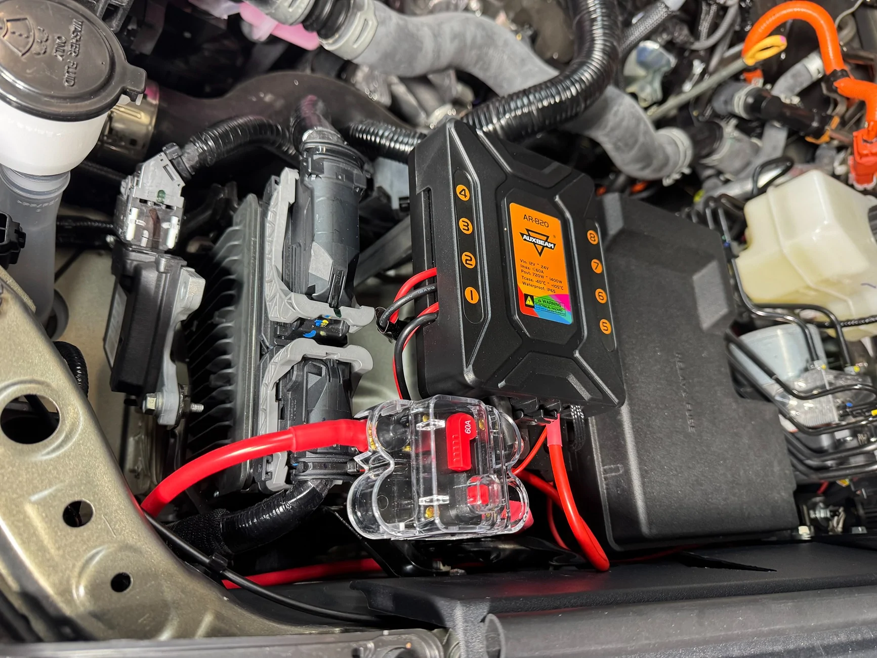
Next, I needed to decide where to mount the switch. I chose not to drill into or mount it on top the fuse box. Instead, I found an opening next to the second fuse, in front of the driver.
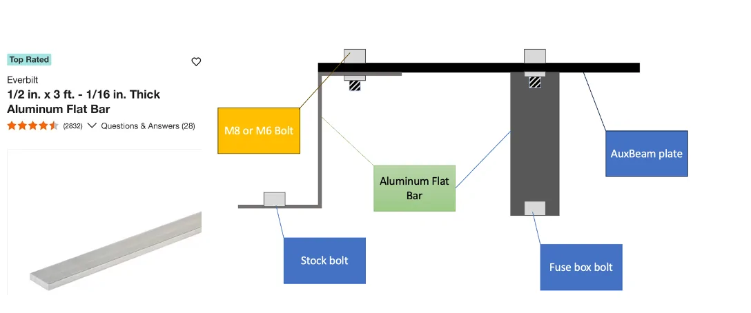
To create a mounting bracket, I went to Home Depot and purchased a 3-foot piece of ½-inch aluminum. This gave me enough material to bend and mount the plate that came with the switch.
I cut the aluminum in half and bent both ends into a Z shape using a large vise, which allowed me to securely mount the switch plate without drilling into the vehicle, and I used the mounting plate that came with the 8-gang switch.


Making and Running the Power Cable
 DO NOT CONNECT THE CABLE TO THE BATTERY AT THIS TIME, and disconnect the negative terminal from the battery. Be careful with your wrench when removing the bolt. If you touch any metal, you will get a big spark. Just from experience.
Purchase a six-gauge battery cable. Approximately 11 feet is required; however, Amazon only sells the cable in 15-foot lengths.
Purchase heavy-duty copper wire lugs sized for six-gauge cable and the appropriate battery terminals. The lug size used was 6 AWG – 5/16 in (M8).
Mount the power distribution plate and the AUXBEAM control panel before cutting the cable. This ensures the correct cable length.
After the mounting locations are confirmed, measure the required length and cut the cable to size.
Strip the insulation from both ends of the cable, exposing enough copper to fully seat inside the wire lugs.
Install the wire lugs onto each end of the cable using a heavy-duty crimping tool. A proper crimp is required for a safe and reliable connection. If a suitable crimping tool is not available, one should be purchased.
For added durability and corrosion protection, apply heat-shrink tubing over the crimped connections.
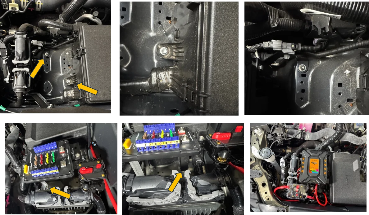
Route the completed power cable from the back seat area toward the front of the vehicle.
Pass the cable through the firewall using an existing rubber grommet to prevent chafing.
Continue routing the cable into the engine bay, securing it away from moving parts, sharp edges, and heat sources.
Now run the switch panel control cable that came with the system, which controls the function from the switch panel through the firewall into the cabin.
When installing cables through a firewall, I highly recommend sealing the entry point ( Inside and outside)with a reliable sealant. For my installation, I used a clear automotive gasket seal. This step is crucial as it helps prevent moisture and air from entering the vehicle, ensuring a secure and dry interior.
During my installation, it was raining heavily, and the next day I noticed significant condensation building up on the inside of my front windshield. This experience reinforced the importance of properly sealing any openings to protect against humidity and ensure a comfortable driving environment.
ACC Fuse Tap Extension
Extend the ACC fuse tap included with the switch system using 14-gauge power wire.
I used a voltage tester to check the fuses in both fuse boxes under the hood. The engine-bay fuse box contains circuits that are either continuously active when the truck is off or inactive when the truck is on. As a result, it does not provide a suitable accessory (ACC) signal. It’s possible that I may have overlooked a circuit during my testing process.
Route the ACC wire to the fuse boxes located under the glove box to obtain a proper accessory-powered source.
I chose to use the USB 2 fuse. If this fuse blows, it will only cause charging issues for the port. This is why I decided to use the USB 2 fuse as the accessory (ACC) signal.
The fuse tap has two fuse openings; install two fuses. When I use just one fuse, the USB-C port does not charge while the switch system is on. After adding two, I resolved this issue.

Connecting All Switch Wires to the Switch Panel
DO NOT CONNECT THE BATTERY AT THIS TIME
To mount the switch panel in the Tacoma, a vehicle-specific dash mount is required. You can use the one that came with the kit or purchase an aftermarket plastic insert mount.
An initial mount was purchased from Tacoma Lifestyle. While the website and ordering experience were good, the mount itself was disappointing. The part was 3D-printed, felt low quality, and did not match the factory interior texture or color. During a test fit, the mounting tabs broke, rendering the mount unusable.
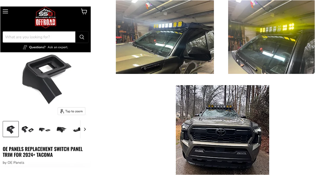
A replacement mount was purchased from Southern Style Offroad. This mount was well-made, closely matched the interior molding, and felt significantly more durable.
Installation of the Southern Style Offroad mount requires cutting an opening so the mount can sit flush. After trimming the opening and cutting the locking area that allows the mount to clip into place, the switch panel fit correctly. Once installed, the panel locked in securely and blended well with the interior.
After mounting the switch panel, connect all switch wires to the panel according to the switch system instructions. Leave the battery disconnected until all wiring has been completed and verified.
Connect all accessories to the switch control panel, paying close attention to the wattage and amperage ratings of each switch output. Ensure that each accessory is connected to an appropriate switch channel based on its power requirements. CONNECT BATTERY AT THIS POINT.
If using accessories with multiple functions, such as a dual-function light bar, separate switch outputs must be used for each function. In this installation, two switch channels were required to support the dual-function light bar.
This completes the switch panel wiring portion of the installation.


This will be my first how-to write-up. This guide is to help Tacoma guys and gals who want to install an AuxBeam switch in their hybrid truck. I searched everywhere for a how-to but couldn’t find one, so here we go.
Power Source Decision
The first thing I needed to figure out was where to pull power from. I had two options:
- The hybrid system under the hood
- The main battery under the back seat
Switch Mounting Location
Next, I needed to decide where to mount the switch. I chose not to drill into or mount it on top the fuse box. Instead, I found an opening next to the second fuse, in front of the driver.
To create a mounting bracket, I went to Home Depot and purchased a 3-foot piece of ½-inch aluminum. This gave me enough material to bend and mount the plate that came with the switch.
I cut the aluminum in half and bent both ends into a Z shape using a large vise, which allowed me to securely mount the switch plate without drilling into the vehicle, and I used the mounting plate that came with the 8-gang switch.
Making and Running the Power Cable
DO NOT CONNECT THE CABLE TO THE BATTERY AT THIS TIME, and disconnect the negative terminal from the battery. Be careful with your wrench when removing the bolt. If you touch any metal, you will get a big spark. Just from experience. Purchase a six-gauge battery cable. Approximately 11 feet is required; however, Amazon only sells the cable in 15-foot lengths.
Purchase heavy-duty copper wire lugs sized for six-gauge cable and the appropriate battery terminals. The lug size used was 6 AWG – 5/16 in (M8).
Mount the power distribution plate and the AUXBEAM control panel before cutting the cable. This ensures the correct cable length.
After the mounting locations are confirmed, measure the required length and cut the cable to size.
Strip the insulation from both ends of the cable, exposing enough copper to fully seat inside the wire lugs.
Install the wire lugs onto each end of the cable using a heavy-duty crimping tool. A proper crimp is required for a safe and reliable connection. If a suitable crimping tool is not available, one should be purchased.
For added durability and corrosion protection, apply heat-shrink tubing over the crimped connections.
Route the completed power cable from the back seat area toward the front of the vehicle.
Pass the cable through the firewall using an existing rubber grommet to prevent chafing.
Continue routing the cable into the engine bay, securing it away from moving parts, sharp edges, and heat sources.
Now run the switch panel control cable that came with the system, which controls the function from the switch panel through the firewall into the cabin.
When installing cables through a firewall, I highly recommend sealing the entry point ( Inside and outside)with a reliable sealant. For my installation, I used a clear automotive gasket seal. This step is crucial as it helps prevent moisture and air from entering the vehicle, ensuring a secure and dry interior.
During my installation, it was raining heavily, and the next day I noticed significant condensation building up on the inside of my front windshield. This experience reinforced the importance of properly sealing any openings to protect against humidity and ensure a comfortable driving environment.
ACC Fuse Tap Extension
Extend the ACC fuse tap included with the switch system using 14-gauge power wire.
I used a voltage tester to check the fuses in both fuse boxes under the hood. The engine-bay fuse box contains circuits that are either continuously active when the truck is off or inactive when the truck is on. As a result, it does not provide a suitable accessory (ACC) signal. It’s possible that I may have overlooked a circuit during my testing process.
Route the ACC wire to the fuse boxes located under the glove box to obtain a proper accessory-powered source.
I chose to use the USB 2 fuse. If this fuse blows, it will only cause charging issues for the port. This is why I decided to use the USB 2 fuse as the accessory (ACC) signal.
The fuse tap has two fuse openings; install two fuses. When I use just one fuse, the USB-C port does not charge while the switch system is on. After adding two, I resolved this issue.
Connecting All Switch Wires to the Switch Panel
DO NOT CONNECT THE BATTERY AT THIS TIMETo mount the switch panel in the Tacoma, a vehicle-specific dash mount is required. You can use the one that came with the kit or purchase an aftermarket plastic insert mount.
An initial mount was purchased from Tacoma Lifestyle. While the website and ordering experience were good, the mount itself was disappointing. The part was 3D-printed, felt low quality, and did not match the factory interior texture or color. During a test fit, the mounting tabs broke, rendering the mount unusable.
A replacement mount was purchased from Southern Style Offroad. This mount was well-made, closely matched the interior molding, and felt significantly more durable.
Installation of the Southern Style Offroad mount requires cutting an opening so the mount can sit flush. After trimming the opening and cutting the locking area that allows the mount to clip into place, the switch panel fit correctly. Once installed, the panel locked in securely and blended well with the interior.
After mounting the switch panel, connect all switch wires to the panel according to the switch system instructions. Leave the battery disconnected until all wiring has been completed and verified.
Connect all accessories to the switch control panel, paying close attention to the wattage and amperage ratings of each switch output. Ensure that each accessory is connected to an appropriate switch channel based on its power requirements. CONNECT BATTERY AT THIS POINT.
If using accessories with multiple functions, such as a dual-function light bar, separate switch outputs must be used for each function. In this installation, two switch channels were required to support the dual-function light bar.
This completes the switch panel wiring portion of the installation.
Sponsored
Last edited:


